Pneumatic Control System Sketch
The General Design Of A Pneumatic System And Its Components
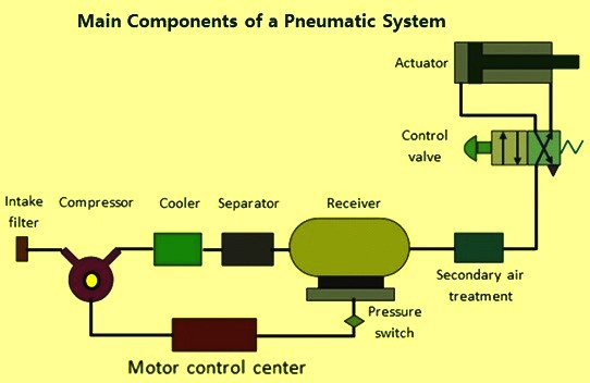
Basics Of Pneumatics And Pneumatic Systems Ispatguru
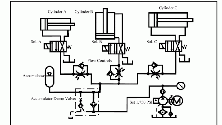
Chapter 5 Pneumatic And Hydraulic Systems Hydraulics Pneumatics
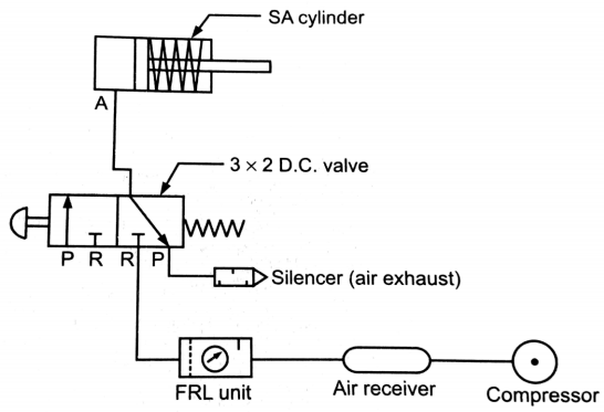
Explain Pneumatic Circuit For Speed Control Of Single Acting Cylinder With Neat Sketch Mechanical Engg Diploma Topicwise Notes And Solutions
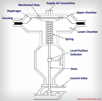
What Is A Pneumatic Actuator Instrumentationtools
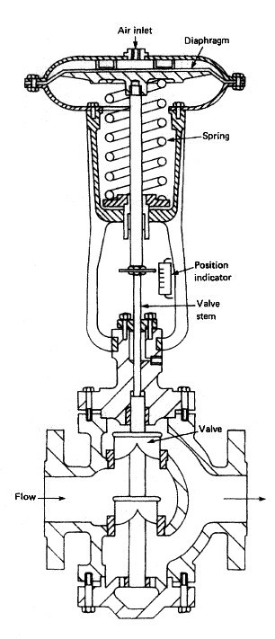
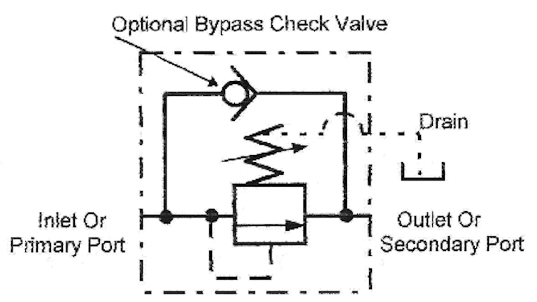
Pneumatic Control Valves For Marine Pneumatic Devices

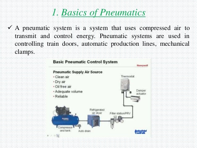
A pneumatic system is a system that uses compressed air to transmit and control energy.
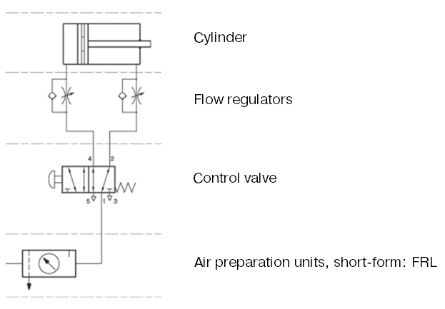
Pneumatic control system sketch.

Block Diagram Of The Pneumatic Actuating System 1 Download Scientific Diagram
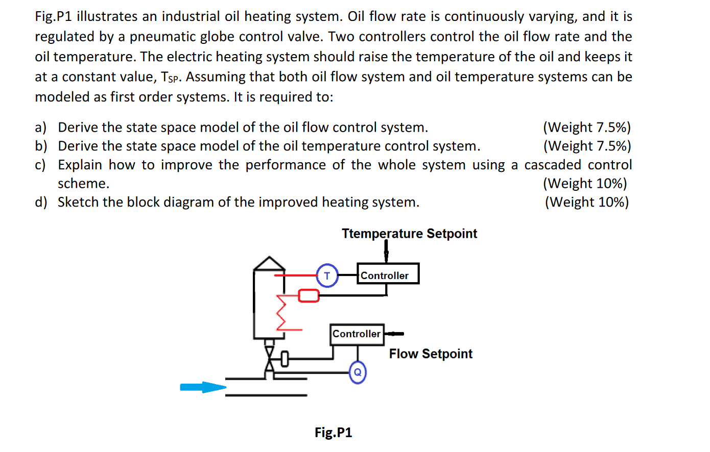
Fig P1 Illustrates An Industrial Oil Heating Syste Chegg Com
Pneumatic Control System
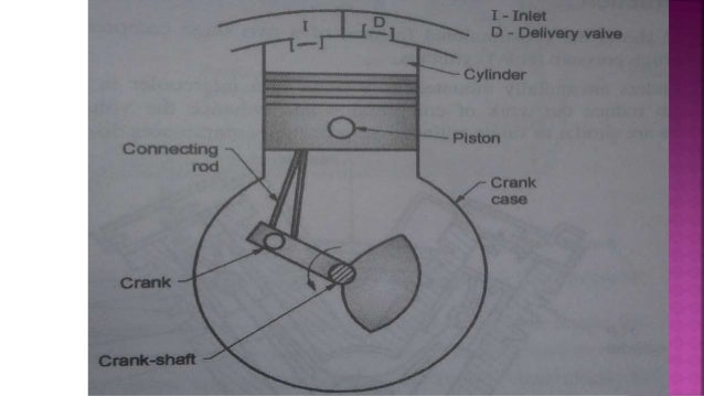
The Basic Components Of A Pneumatic System
How To Analyze And Troubleshoot Hydraulic Circuit Problems Youtube Hydraulic Systems Hydraulic Circuit

Pneumatic Pid Controllers Closed Loop Control Systems Automation Textbook

Pneumatic Controller With A Restriction In The Feedback Path Which Download Scientific Diagram
Http Www Smcpneumatics Com Pdfs Smc Basic Pneumatics Pdf

How To Read A Spool Valve Schematic Drawing Realpars
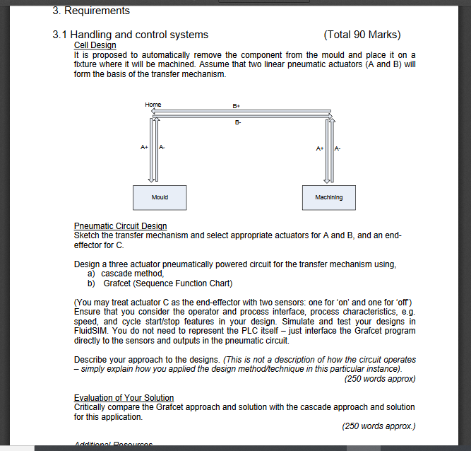
Work Out The Sequence For This System Sketch A Tr Chegg Com
Pneumatic Control System Its Components
Modul Pneumatic

Instrumentation And Control Basic Pneumatics Docsity

3 2 Way Pneumatic Valve How They Work Tameson

Solved The Schematic Below Shows The Air Conditioning Sys Chegg Com
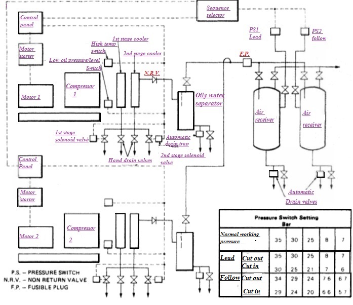
Air Compressors Automatic Operation Control System Air
Instrumentation Today Control Valve Pneumatic Sketch

We Are Specialists In Pneumatic Control System Design For New Projects Process Improvements And Health S Process Improvement Health And Safety Circuit Design
Https Encrypted Tbn0 Gstatic Com Images Q Tbn 3aand9gcqqr6gmpnpqm8lzcytdp6zthdbuiafo8dqatxs1pjyfyh7aycwi Usqp Cau

Lecture 29 Pneumatic Control Systems I Youtube

Taking The Guesswork Out Of Pneumatic Control Crossco

The Pneumatic Pid Controller S Working Principle Visaya

Pneumatic Relay Pressure Measurement Industrial Automation Plc Programming Scada Pid Control System
Book 2 Chapter 20 Sequence Valves Hydraulics Pneumatics
Source : pinterest.com
