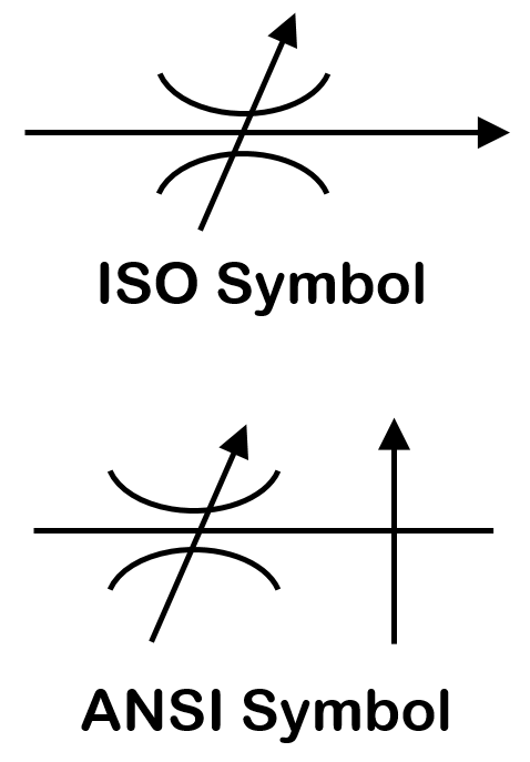
Pneumatic Speed Control Valve Symbol

Reading Fluids Circuit Diagrams Hydraulic Pneumatic Symbols

Tip 14 Go With The Flow Control Hydraulics Pneumatics
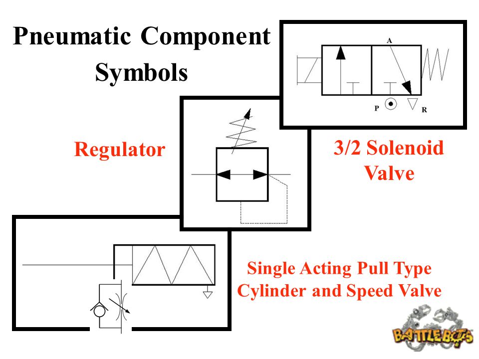
Pneumatic Circuit Symbols Explained Library Automationdirect
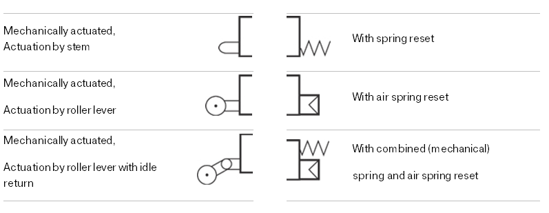
Pneumatic And Hydraulic Actuation System Cont Ppt Video Online Download

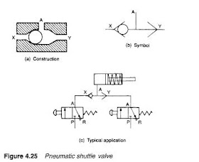
Untangling Pneumatic Circuit Symbols Hydraulics Pneumatics
Valves Which Control The Direction Of The Flow Of The Compressed Air Spool Valves

3 2 mechanical valve with integrated exhaust port basic.
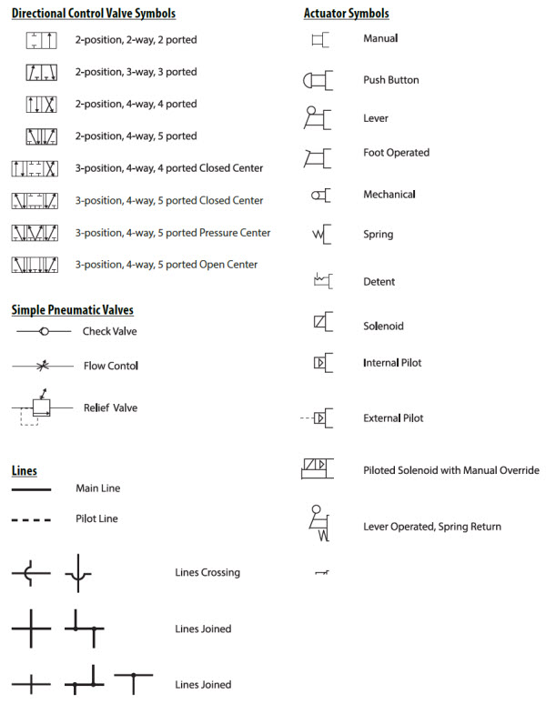
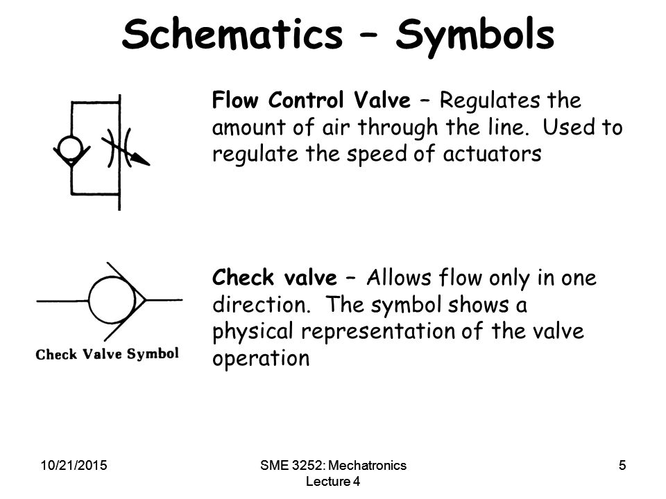
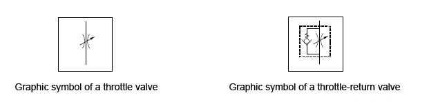
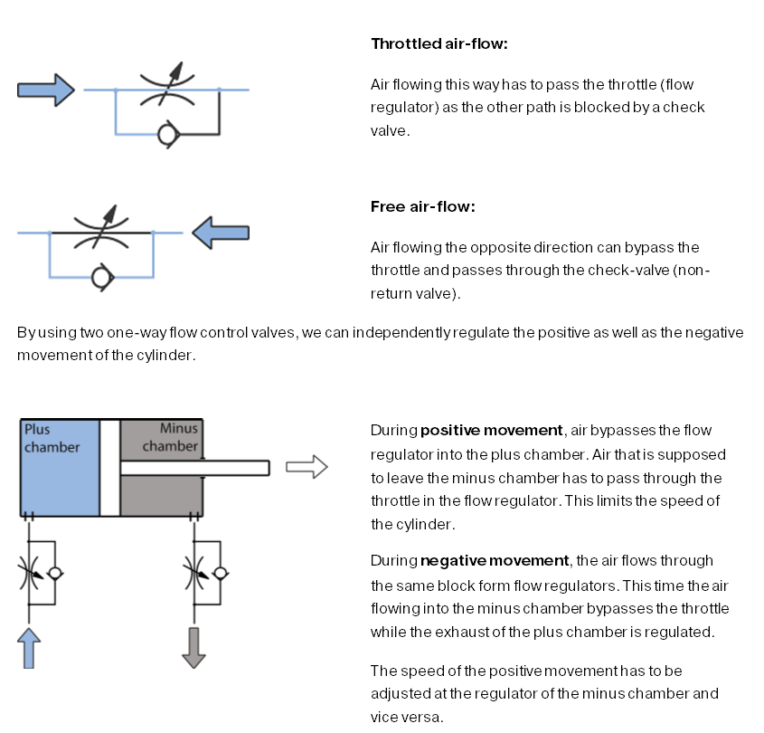
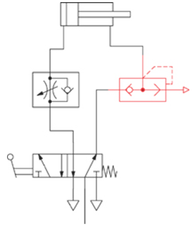
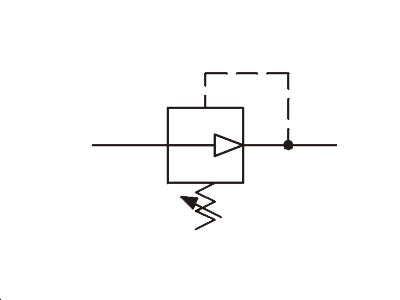
Pneumatic speed control valve symbol.
The Pneumatic Cylinder Part 2

Pneumatics Symbols Din Iso1219 1 03 96 Graphic Symbols For Pneumatic Equipment Volume Symbol Description Alexander Ospina Academia Edu
Iso Schemes Of Directional Control Valves

Pneumatic Symbols Pneumatics Guides Rowse Pneumatics

Pneumatic Misc

Hydraulic Valve Symbols Google Search Studying Math Hydraulic Mechatronics
Using Graphic Symbols To Illustrate Basic Circuit Designs Ppt Video Online Download
Engineering Types Of Control Valves Part 2

Application Notes Speed Control Actuator Synchronisation Hydraulics And Pneumatics

5 2 4 2 Way Pneumatic Valve How They Work Tameson
How Does A Pressure Compensated Flow Control Valve Work Engineering360
Grouping And Construction Of Control Valves

Hydraulic Restriction Check Valves Hydraulic Valve

Common P Id Symbols Used In Developing Instrumentation Diagrams Learning Instrumen Piping And Instrumentation Diagram Control Engineering Process Engineering

Actuators An Overview Sciencedirect Topics

3 2 Way Pneumatic Valve How They Work Tameson

Directional Control Valve Directional Control Valve Mechanical Drawing Symbols Typical Hydraulic Cylinder Control Schematic

Hydraulics And Pneumatics Pages 101 150 Flip Pdf Download Fliphtml5
Https Encrypted Tbn0 Gstatic Com Images Q Tbn 3aand9gcq0mfzsen8erkzkmsrwfzek8i2l91jdfsxsdcekaheymmevuvgl Usqp Cau

Book 2 Chapter 5 Counterbalance Valve Circuits Hydraulics Pneumatics
Online Pneumatics Quiz Gpm Hydraulic Consulting Inc
Gain Control Of The Flow Hydraulics Pneumatics
Mechanical Engineering Basic Pneumatic Training Course

Solenoid Valves Discrete Control System Elements Automation Textbook
Source : pinterest.com
